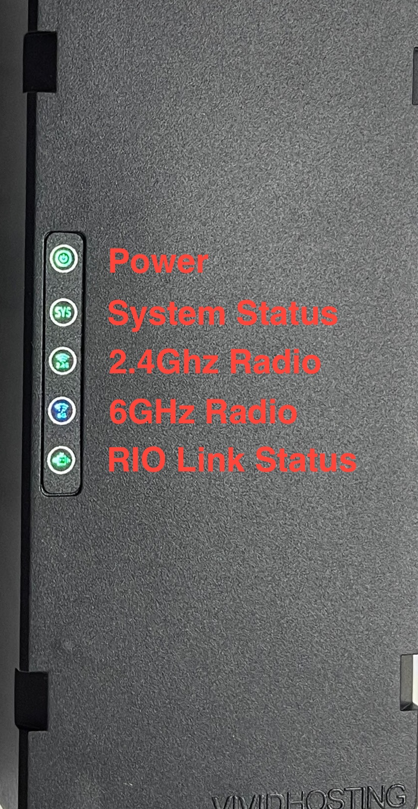
CSA/FTA(A)/Team Reference

Robot Radio Lights
Robot Radio, No Link to Field AP
PWR
Green
SYS Green Blink
2.4G Off
6G Off
Rio Green
Robot Radio, No Link to Field AP, Programmed using WPA Kiosk
PWR
Green
SYS Green, Blink/Blink/Pause (.._.._) pattern
2.4G Off
6G Off
Rio Green
Robot Radio, Linked to Field AP
PWR
Green
SYS
Green
2.4G Off
6G Blue
Rio Green
AP Mode Look Out For
PWR
Green
SYS
Green
2.4G Off
6G Off
Rio Off
RoboRIO Lights
Power
OK Green
Brownout Orange
Fault, check for short Red
Status
OK Off
Booting Orange
Unrecoverable error Orange Blink
Radio
Ignore
Comm
No Comms Off
Comms, no code Red Blink
E-Stop Red
OK Green
Mode
Disabled Off
Auto Orange
Teleop Green
Test Red
SystemCore Lights
Power
Normal Operation Green
No power / Reverse Polarity Off
Mode
Robot On and Disabled Orange
Robot On and Enabled Orange Blink
RT Subsystem disabled Off
Status
Uncleared hardware fault; Red
Brownout protection enabled*
Display hardware fault Red Slow Blink
CAN Bus Fault Red Fast Blink
No faults Off
*Brownout protection is disabled in Alpha Image 157. Brownout protection will disable PWM and digital outputs.

REV Motor Controller Lights
Brushed Mode
Brake No Signal Blue Blink
Brake Valid Signal Blue
Coast No Signal Yellow Blink
Coast Valid Signal Yellow
Brushless Mode
Brake No Signal Cyan Blink
Brake Valid Signal Cyan
Coast No Signal Magenta Blink
Coast Valid Signal Magenta
Movement
Partial Forward Green Blink
Full Forward Green
Partial Reverse Red Blink
Full Reverse Red
Forward Limit Green / White Alternating
Reverse Limit Red / White Alternating
Identification, Updating, and Recovery
Identify Magenta / White Fast Alternating (4 Hz)
CAN Firmware Updating Yellow / White Slow Alternating
CAN Firmware Retry Blue / White Slow Alternating
USB Device Firmware Update Off
Recovery Mode Off
Fault Conditions
12V Missing Blue / Orange Slow Alternating
Sensor Fault Magenta / Orange Slow Alternating
Gate Driver Fault Cyan / Orange Slow Alternating
CAN Fault Yellow / Orange Slow Alternating
Corrupt Firmware Off
CTRE Motor Controller Lights
Disabled Codes
No Power Off
CAN bus/PWM is not detected Red Alternating
CAN bus detected, Phoenix not running on robot Orange Alternating
CAN bus detected, robot disabled Orange Simultaneous Blink
Enabled Codes
Enabled, no output Orange
Reverse Movement Red Simultaneous Blink
Forward Movement Green Simultaneous Blink
Limit hit. Direction of blink indicates forward/reverse. Red Alternating Blink Followed by Off
Special Codes
Thermal Shutoff Orange Alternating Blink Followed by Off
Unlicensed Phoenix Pro Red / Green Alternating Blink
Hardware Damage Red / Orange Alternating Blink
Bootloader Red / Orange Alternating Blink, Right Side Only
CTRE CANivore Lights
STAT
No Power Off
Powered but USB not plugged in Red Double Blink
USB plugged in but no comms Red Fast Strobe
CAN disabled, no power Orange Double Blink
CAN disabled Orange Fast Strobe
CAN enabled, no power Green Double Blink
CAN enabled Green Fast Strobe
Hardware Damage Red / Orange Fast Alternating
Bootloader Green / Orange Fast Alternating
WIFI
Wi-Fi Enabled Green Fast Blink
Wi-Fi Disabled Off
BT
Bluetooth Enabled Green Fast Blink
Bluetooth Disabled Off
CAN (double blink = termination disabled)
Voltage too low for CAN bus Red
No CAN comms Red Fast Strobe
CAN 2.0b legacy mode Orange Fast Strobe
CAN FD Active Green Fast Strobe
CTRE CANcoder Lights
(dim = no CAN)
No Power Off
CAN bus lost Red Blink
Magnet is out of range (<25mT or >135mT) Red Fast Strobe
Magnet in range with slightly reduced accuracy (25-45mT or 75-135mT) Orange Fast Strobe
Magnet in range (between 45mT-75mT) Green Fast Strobe
Hardware Damage Red / Orange Alternating
Bootloader Green / Orange Alternating
CTRE Pigeon Lights
No Power Off
No CAN bus detected Red Alternating
CAN bus detected, Phoenix not running on robot Orange Alternating
CAN bus detected. Robot disabled. Orange Simultaneous Blink
CAN bus detected. Robot enabled. Green Alternating
Hardware Damage Red / Orange Alternating
Bootloader Red / Orange Alternating Blink, Right Side Only
Thrifty Nova Lights
Fatal fault Red Fast Alternating
Encoder not connected or invalid Orange Simultaneous Blink (10 Hz)
Enabled but output power is 0% Yellow Fast Alternating
No CAN data detected Yellow Fast Simultaneous Blink
CAN detected but no control frames Yellow
Forward motion. Flash rate = speed Green Simultaneous Blink
Reverse motion. Flash rate = speed Red Simultaneous Blink
Motor halted. High temperature >90°C Orange Fast Simultaneous Blink
Warning. Approaching thermal limit >75°C Orange Fast Simultaneous Blink (20 Hz)
Redux CANANDMAG Encoder Lights
Magnet is in range Green
Magnet is not in range (typically too far) Red
Firmware update in progress Cyan Blink
CAN ID conflict detected Blue Blink
Hardware fault Red Blink
Encoder zero button pressed White
Dim Undervoltage Dim Blue
Redux CANANDGYRO IMU Lights
Normal operation, roboRIO detected on CAN bus Green Slow Blink
roboRIO not detected or other CANbus faults Red Slow Blink
Calibrating, operational with reduced accuracy Yellow
DFU in progress Blue Blink
DFU failed, check Alchemist Blue
Hardware fault Yellow / Red Alternating
CAN ID conflict detected Blue / Red Alternating
Grapple MitoCANdria Lights
In bootloader Red
Bootloader initialized Red / Yellow Alternating
Detecting CAN bitrate Red / Purple Alternating
Firmware ready, CAN initialized Green
Firmware ready, CAN awaiting bitrate detection (CAN bus disconnected) Green / Purple Alternating
Grapple LaserCAN Lights
P (Power)
No Power Off
Power On Green
S (Status)
Normal operation. Will flash at speed proportional to the distance it's reading. Orange Blink
In bootloader, awaiting firmware update Orange

FRC Basic Wiring Diagram Layout of the core components of the control system and introductory information for them

Diagram courtesy of FRC® Team 3161 and Stefen Acepcion.

FRC REV Wiring Diagram Layout of all popular components of the control system including REV Control System Components

Diagram courtesy of FRC® Team 3161 and Stefen Acepcion.

FRC CTRE Wiring Diagram Layout of all popular components of the control system including CTRE Control System Components

Diagram courtesy of FRC® Team 3161 and Stefen Acepcion.

FTC Wiring Diagram (B1 - Basic) Basic Control Hub RC Diagram

Diagram courtesy of FRC® Team 3161 and Stefen Acepcion.

FTC Wiring Diagram (B2 - Advanced) Advanced Control Hub RC Diagram

Diagram courtesy of FRC® Team 3161 and Stefen Acepcion.


Limelight ChArUco Calibration ChArUco Calibration Board

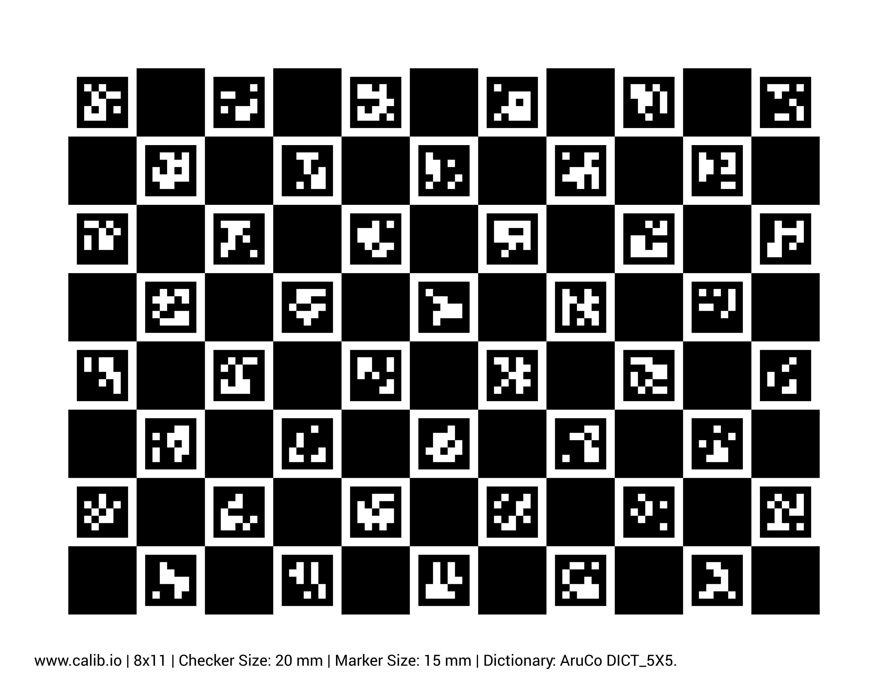
Note: The ChArUco board is intended to be viewed on a large tablet

Width: 11 markers
Height: 8 markers
Dictionary: 5x5_100

Important! The square size and marker size must be accurately measured for proper calibration. Use calipers to measure the side lengths of a black square and inner marker in millimeters. The sizes shown on the board will be inaccurate.


Component Manuals
Software Documentation
Keyboard Shortcuts

Driver Station

F1 Joystick rescan
[ + ] + \ Enable Robot
Enter Disable Robot
Space E-Stop
Team IP Addresses

IP Address Subnets

Team 1 10.0.1.x
Team 12 10.0.12.x
Team 123 10.1.23.x
Team 1234 10.12.34.x
Team 12345 10.123.45.x

IP Addresses

Robot Radio 10.TE.AM.1
roboRIO/SystemCore 10.TE.AM.2
roboRIO USB 172.22.11.2
roboRIO Name roborio-TEAM-frc.local
SystemCore Wi-Fi 172.30.0.1
SystemCore USB (Windows) 172.28.0.1
SystemCore USB (Mac/Linux) 172.29.0.1
Field AP 10.TE.AM.4
Driver Station 10.TE.AM.5
(subnet 255.0.0.0)
Helpful Commands
ncpa.cpl Network adapters
wf.msc Windows firewall
ipconfig Show network settings
ipconfig /release Release DHCP address
ipconfig /renew Acquire DHCP address
ping 10.TE.AM.255 Scans network
arp -a Shows reachable IPs


Have a request for something to be added? Create an issue or PR on GitHub or post on Chief Delphi! :)